
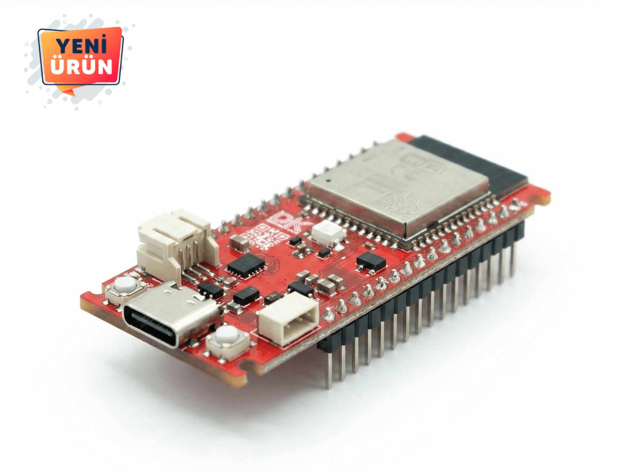
DENEYAP Kart v2 (Type-C)
DENEYAP Kart v2 is a development board powered by the ESP32-S3-WROOM-1 module. It is equipped with Wi-Fi, Bluetooth, and built-in sensors. It provides Arduino IDE compatibility and easy programmability. It offers features such as a dedicated Li-Po connection connector, expandable memory capacity, and Bluetooth 5 support. NOTE: To program the Deneyap Kart V2 for the first time, a manual boot process is required. This process is only necessary once, before the initial code upload. For the manual boot process, after connecting the card to the computer, press and hold the “BUTON” button on the card while pressing the “RESET” button. The initial code upload process is then performed.
DENEYAP Kart v2
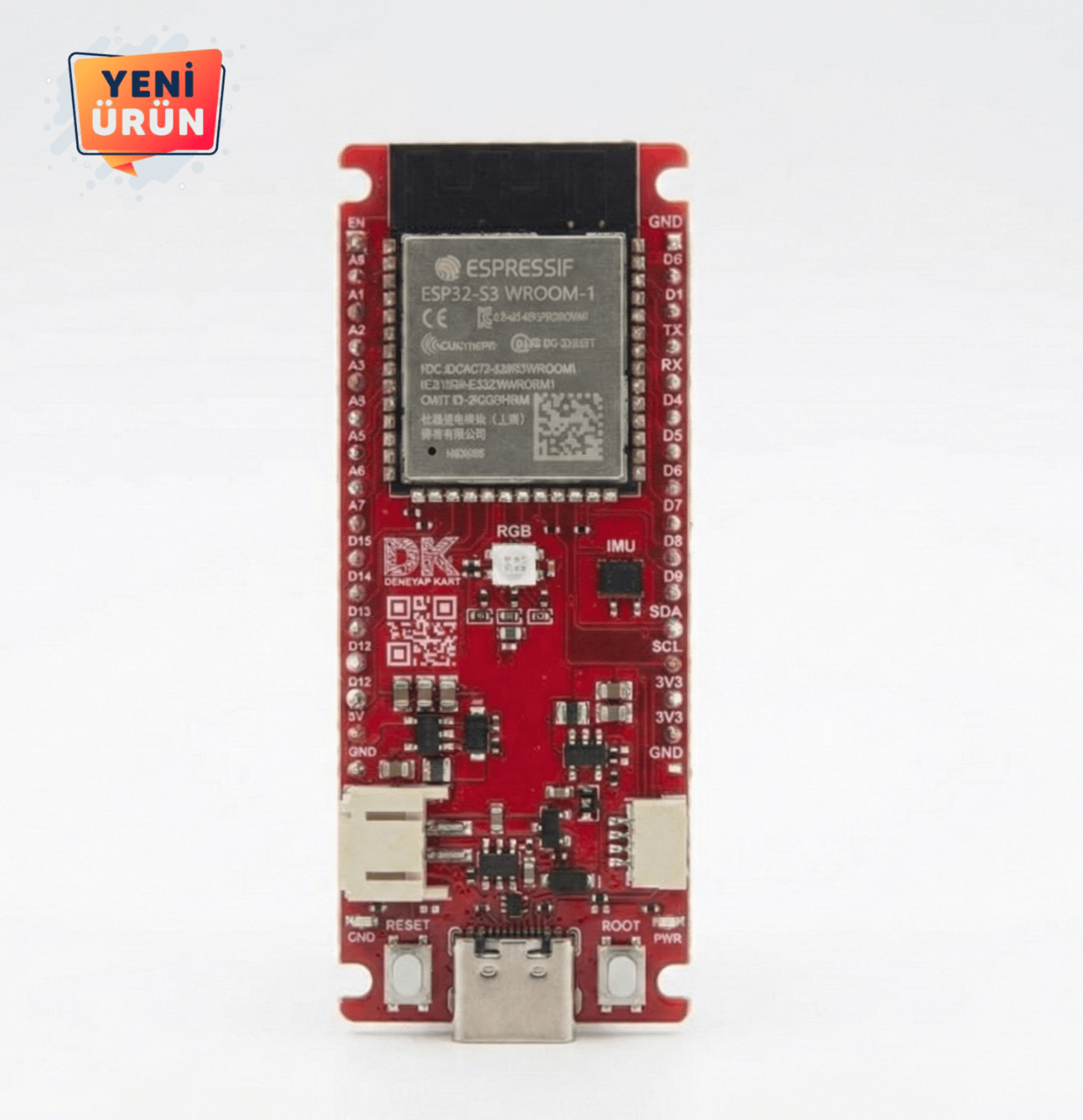
One of the versatile and powerful electronic development boards in the Deneyap family, DENEYAP Kart v2 has been developed using the ESP32-S3-WROOM-1 module.
With the new generation powerful dual-core Xtensa LX7 microprocessor, you can start machine learning and artificial intelligence-based projects with Tensorflow Lite.
Thanks to its built-in Wi-Fi and Bluetooth communication features, it will enable you to prepare Internet of Things and cloud-based projects.
Using the Wi-Fi communication feature, you can exchange data between your system and your cloud-based application. In addition, you can use your card as a server and thus set up your own closed-loop wireless communication network.
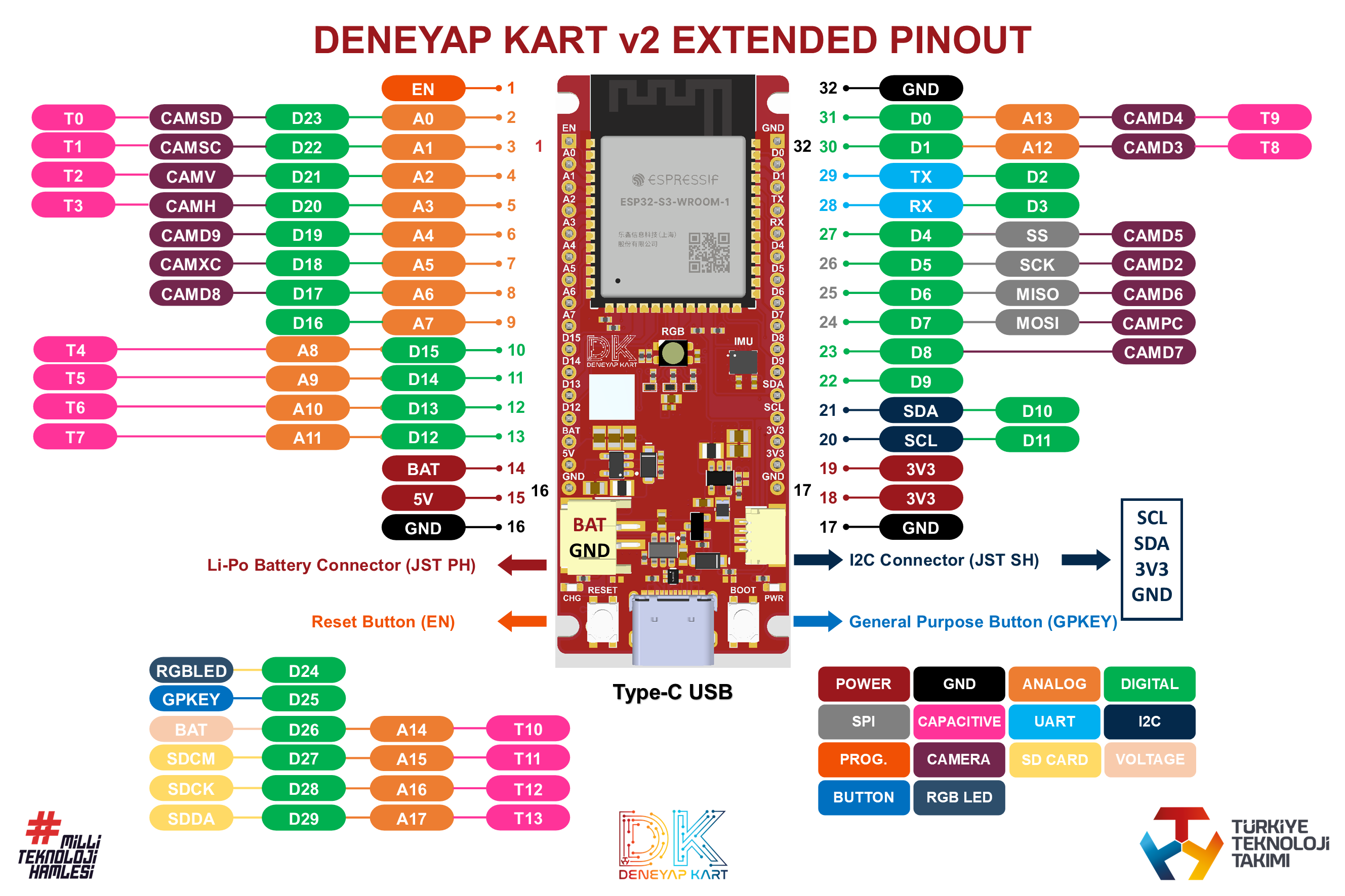
It has a wide range of peripheral connections such as ADC, PWM, UART, SPI, I2C, TWAI, I2S, Capacitive Sensing, LCD, DVP, RMT, SD/SDIO/MMC, JTAG, Timer, pulse counter, and external interrupt. Furthermore, to provide you with flexibility, some of these connection interfaces can be used from any pin according to your needs.
It has an integrated internal temperature sensor.
It has 23 pins that can be used for general purposes.
There is a dedicated Li-Po connection connector to help you reliably power your system. Moreover, you can charge your Li-Po battery using this connection connector. You can also monitor the charge level of the connected battery.
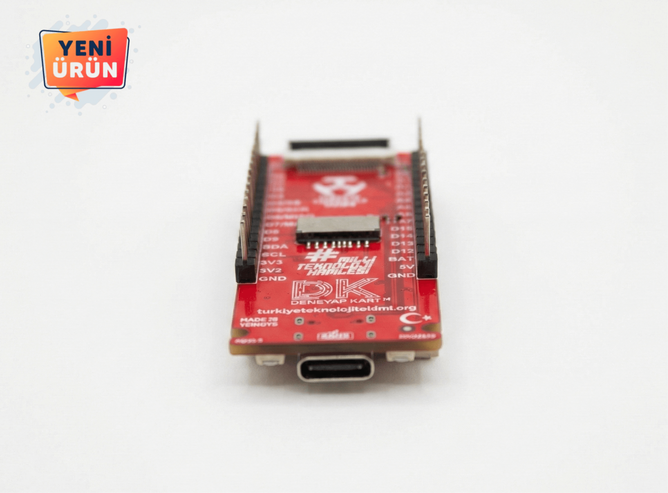
The back of the card features a micro SD card connector and an FPC camera connector for connecting the Deneyap Camera.
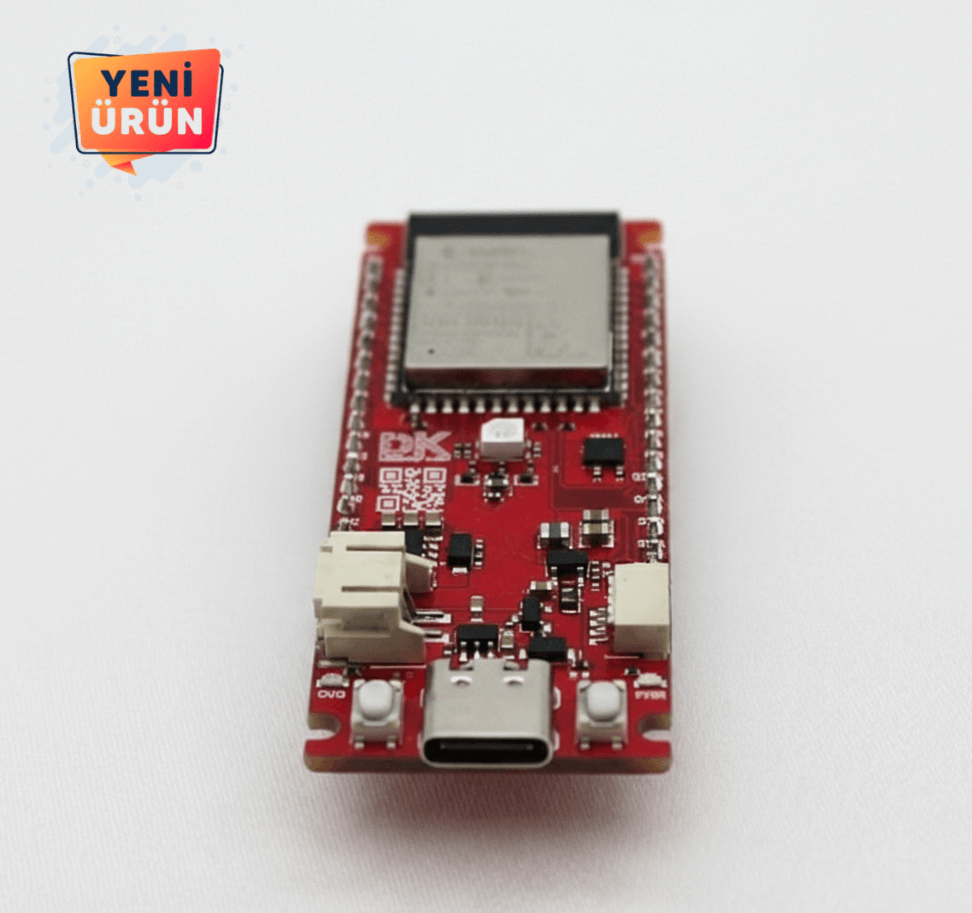
It also has 2 buttons and 1 addressable RGB LED built-in.
Using the I2C communication connector, you can quickly bring your system consisting of sensors and actuators to life without cable connections or soldering.
You can get 3.3V and 5V voltage outputs to use in peripheral devices that will provide uninterrupted external connection from your board. Even when powering your system with a Li-Po battery, the 5V power output will always be available to you.
DENEYAP Kart v2 has a design compatible with breadboards. The pins are soldered for you so you can start developing immediately.
DENEYAP Kart v2 is compatible with the Arduino IDE. You can start coding using the instructions.
The signal processing and machine learning performance of DENEYAP Kart v2 has been enhanced compared to the first version thanks to the artificial intelligence (AI) accelerator of its new generation LX7 processor.
The DENEYAP Kart v2 has Bluetooth 5 instead of Bluetooth 4.2, enabling data exchange via long-range (1 km and above) Bluetooth communication called Coded PHY.
The DENEYAP Kart v2 can measure motion and ambient temperature data thanks to its built-in IMU and built-in temperature sensor.
NOTE: To program the Deneyap Kart v2 for the first time, a manual boot process must be performed on the card. This process is performed only once, prior to the initial code upload. To perform the manual boot process, connect the card to the computer via a USB cable, press and hold the “BUT” button on the card, then press and release the ‘RES’ (reset) button, and finally release the “BUT” button. After completing these steps, the first sample code can be loaded onto the card. (The manual boot process is only required for the first use; subsequent programming can be done by directly loading the code.)
Promotional Video

Other Products

DENEYAP Relay


Robotics Programming Set

DENEYAP Development Kit

DENEYAP Pressure Sensor


DENEYAP Soil Moisture Sensor


DENEYAP 5x7 LED Matris

DENEYAP Touch Keypad


DENEYAP Speaker

DENEYAP Kart 1A v2 (Type-C)


DENEYAP OLED Display

DENEYAP Card Female Pin

The DENEYAP Mini

DENEYAP Microphone

DENEYAP Mini v2 (Type-C)

Aviation Set


DENEYAP Kart 1A

Li-Polymer Batary


DENEYAP Joystick


DENEYAP Depth Sensor

DENEYAP Camera

